Planning a complete beverage production line for a new factory starts with the drink and finished package. Those choices determine the processing route, container supply, filler, downstream equipment and utilities. A workable plan also assigns each equipment interface to an owner, so the line can be installed and tested as one production system.
Set the design basis before choosing machines
Write a product-and-package matrix for every planned SKU: beverage type, relevant product properties, container drawing, closure, label, secondary pack and required shelf-life approach. Add the target accepted finished output, operating schedule and expected changeovers. The number of cycles listed for a filler alone cannot define what the factory will ship.
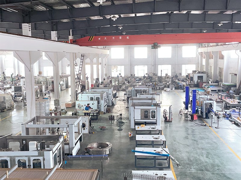
Next, document the site. Include a scaled building drawing with columns, doors, clear height, drainage points, loading routes and available utility connections. A line arrangement must allow operators to replenish materials and technicians to reach equipment safely, not merely fit the machines inside the room. Sidel's complete-line overview similarly treats space, production targets and packaging formats as linked design inputs.
The equipment path below is conditional. A PET bottled-water project, a carbonated drink project and a juice project can share some packaging stages while requiring different preparation and filling processes. MIC's water filling line illustration shows one possible connected arrangement, not a fixed layout for every beverage.

MIC website illustration of a bottled-water line; actual new-factory layout depends on the product, building and project scope.
Water treatment and beverage pretreatment
Water treatment should be specified against the incoming water analysis and the quality needed for the product and process. Identify the raw-water source, expected variation, treated-water uses, storage and points of use before selecting filtration or other treatment stages. Water that is suitable for one beverage may still affect the taste or stability of another; Tetra Pak's juice-processing reference discusses this for reconstitution water.
Keep product water, cleaning water and other utility water demands visible in the balance. Ask who supplies and tests the treatment system, the storage tanks and the piping to each user. MIC shows water-treatment equipment within its water-line offering; the final treatment train requires the project's water report and product requirements.

Water-treatment equipment pictured on the MIC website; treatment steps must follow the site's water analysis.
Pretreatment turns ingredients into a beverage suitable for the selected filling process. A carbonated drink may need syrup preparation, proportioning, cooling and carbonation. Juice, tea or another formulated drink may require different mixing and thermal treatment. The recipe and food-safety design determine the sequence; there is no single pretreatment skid for every product. MIC's carbonated-beverage pretreatment page is a relevant equipment reference for that application.
Define the handoff from pretreatment to filling: required product condition at the filler inlet, flow range, hold or buffer arrangement, cleaning connections, instruments, alarms and responsibility for off-specification product. These interfaces should appear on the process flow diagram and later on the piping and instrumentation drawings.
Container supply and PET blow molding
A PET project may blow bottles from preforms on site or bring in finished bottles. On-site blow molding changes the scope of preform handling, molds, high-pressure air, cooling, bottle transfer and quality inspection. Purchased glass bottles or cans require a different empty-container supply and handling route. Sidel's water-line equipment overview shows how preform feeding, blowing and filling can be considered together in a PET line; its configurations and output figures are specific to Sidel.
Freeze the container drawing before the filler and guides are finalized. Neck finish, base geometry, weight and dimensions affect the mold, capper and conveyor interfaces. Plan how empty containers reach the filling area without damage, and record whether any air conveyor, infeed conveyor or depalletizer belongs to the machine supplier or another contractor.

PET bottle blowing pictured on the MIC website; bottle geometry and supply method are project inputs.
Filling and closure
Select the filling and closing equipment for the actual drink, container and shelf-life process. Carbonated drinks, still water and heat-treated products can need different product conditions and filling methods. The closure system must match the bottle finish or can end, and the line needs a defined inspection and reject path for defective packages.
The supplier discussion should separate machine cycle rate from accepted output under the agreed package and product conditions. Ask for the machine's interface requirements, format-change scope, cleaning route, product-contact boundary, control signals and utilities. MIC's beverage filling line category provides examples of bottle and can equipment; the project specification determines which configuration is appropriate.
Labeling, coding and secondary packing
Choose labeling from the finished container and brand pack: label material, application method, position, package shape and required line speed all matter. Coding needs a defined location and legibility check after filling or packing, according to the product's traceability plan. Reserve space for label-roll changes, inspection access and reject handling.
Secondary packing may use shrink film, trays, cartons or another distribution pack. Define how many containers form a pack, how the pack is checked and what happens to a rejected container or incomplete group. MIC lists rear packaging equipment; the supplied packer and format should follow the buyer's finished-pack specification.
Conveyors, accumulation and palletizing
Conveyors link machines with different operating rhythms. The design must cover bottle stability, transfer heights, accumulation, line-stop signals and restart behavior. A downstream packer stop should have a defined effect on the labeler and filler, with enough controlled accumulation for the intended operating case. Draw each connection and assign the controls interface to a responsible party.
Palletizing is a separate decision from packing. Some projects may start with manual pallet loading; others require a palletizer and stretch wrapper. Define pallet pattern, pack dimensions, pallet type, warehouse handoff and traffic route before sizing the end-of-line area. The MIC rear packaging page shows palletizing among possible downstream functions, without establishing it as a standard component of every line.
Utilities and factory layout
Prepare a utility schedule for each machine and for the line as a whole. Include electrical supply, process and cleaning water, compressed air, chilled water or cooling, steam or another heat source where required, CO2 where required, drainage, wastewater and ventilation. The exact demand depends on the selected equipment and operating case; request supplier data rather than copying a generic consumption table.
On the layout, trace four flows: ingredients and treated product, empty containers and packaging materials, people and maintenance access, and finished packs to storage. Show cleaning chemical storage and drainage where the process requires them. Reserve clearance to remove parts, change molds or formats, open guards and service motors. Leave future expansion space only where it has a defined purpose and access route.
Use an interface register to integrate the line
An equipment list says what is purchased. An interface register says how those purchases connect. Give every boundary an upstream and downstream owner, a drawing reference and a verification step:
- Physical: position, elevation, conveyor transfer, access and guarding.
- Process: flow, pressure or temperature at the handoff where relevant, product hold-up and cleaning route.
- Utilities: connection size and location, supply quality, peak demand and drainage responsibility.
- Controls: start/stop permissions, starved and blocked signals, alarms, recipe or format data and network ownership.
- Quality: sampling point, reject route, traceability and acceptance record.
Review these interfaces at design approval, during the factory acceptance test for the assembled scope, and again after installation. Site acceptance must cover the connections and utility conditions that the supplier's factory could not reproduce.
What to send with a new-factory RFQ
A useful first package contains the product-and-SKU matrix, container and closure drawings, label and finished-pack samples, target accepted output, raw-water report, factory CAD drawing and known utilities. Add the intended operating schedule, cleaning approach, future formats and a list of equipment already selected or owned by others.
Ask the supplier to return a process flow diagram, equipment list, preliminary layout, utility schedule, interface/responsibility matrix and proposed acceptance boundaries. These documents let the buyer compare complete scopes and identify missing work before construction or equipment fabrication begins.
FAQ
Does every beverage factory need PET blow molding?
No. PET bottles may be blown on site or supplied as finished containers. Glass bottles and cans use other container-handling arrangements. The choice changes equipment, storage, utilities and layout.
Can one line produce water, juice and carbonated drinks?
Compatibility depends on the selected processing, filling and cleaning design, as well as each container and closure. List every proposed product and format in the RFQ and request a separate operating case for each one.
Is palletizing part of a complete line?
It may be included, optional or handled by the buyer. The correct scope depends on pack format, output, labor plan and warehouse flow. Define the handoff from the packer to the pallet before finalizing the equipment list.
What is the first drawing a new factory needs?
Start with a product-and-package matrix and a process flow diagram, then place the major equipment on a scaled building plan. The layout can be refined as utility data, machine dimensions and responsibility boundaries are confirmed.
Final thoughts
A complete line proposal is useful when the equipment, building and responsibilities describe the same production case. Start with the drink and finished pack, then ask MIC to review the proposed equipment scope against your factory drawing, raw-water report, utility conditions and target accepted output.