The carbonated beverage filling machine working principle relies on controlled pressure. Before liquid enters, the filler brings the container and product side to compatible pressure conditions. It then controls the fill and releases headspace pressure in stages to limit foaming and CO2 loss. The exact cycle varies with the beverage, container, valve design, and line configuration.

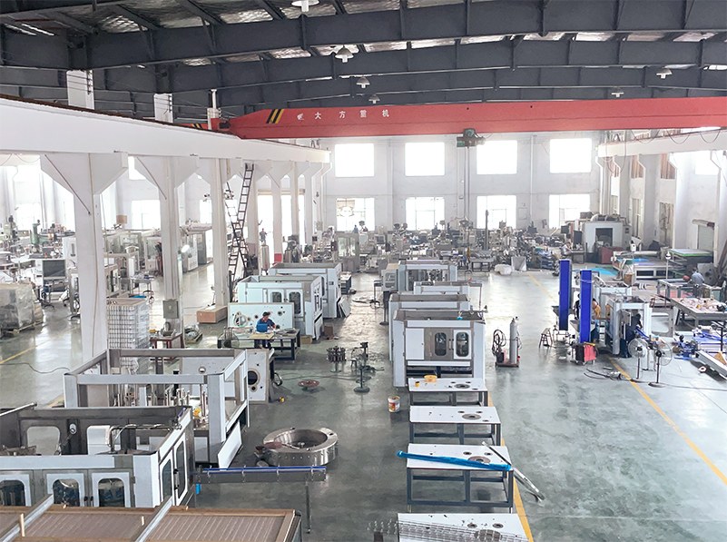
Figure 1. Carbonated drink filling line shown as a complete-line layout. Source: MIC carbonated drink filling machine page.
What is a carbonated beverage filling machine
A carbonated beverage filling machine transfers a carbonated product into bottles or cans while controlling the pressure changes that can release dissolved CO2. Typical applications include carbonated soft drinks, sparkling water, soda water, and other beverages whose gas content must be protected during filling.
The term may describe a standalone filler, a filler and closer monoblock, a rinser-filler-capper, or a complete carbonated drink filling machine project. A complete project may also cover product preparation, carbonation, container production or feeding, inspection, labeling, and secondary packaging. Confirm the scope early because two quotations can use the same equipment name while covering different responsibilities.
Why do carbonated drinks need counter-pressure filling
Carbon dioxide remains dissolved while product conditions and pressure stay suitable. A sharp pressure drop lets gas escape, which can cause heavy foam, unstable fill levels, product loss, and lower retained carbonation. Counter-pressure filling seals the container against the valve and brings it to controlled pressure before liquid enters, reducing that sudden change.
The terms "counter-pressure filling" and "isobaric filling" are often used for this general approach. They do not define one universal valve design. A machine may use liquid-level control, a return-gas tube, an electrical probe, or volumetric measurement. Purging, pre-evacuation, filling speed profiles, and pressure-release steps also vary.
Temperature also affects beverage behavior and CO2 retention, but no single filling temperature suits every product. The supplier needs the product specification and intended operating window before selecting a machine or confirming output.
Carbonated beverage filling machine working principle
Most industrial counter-pressure systems follow the same broad logic. The details below describe a general cycle, not a fixed sequence for every filler.

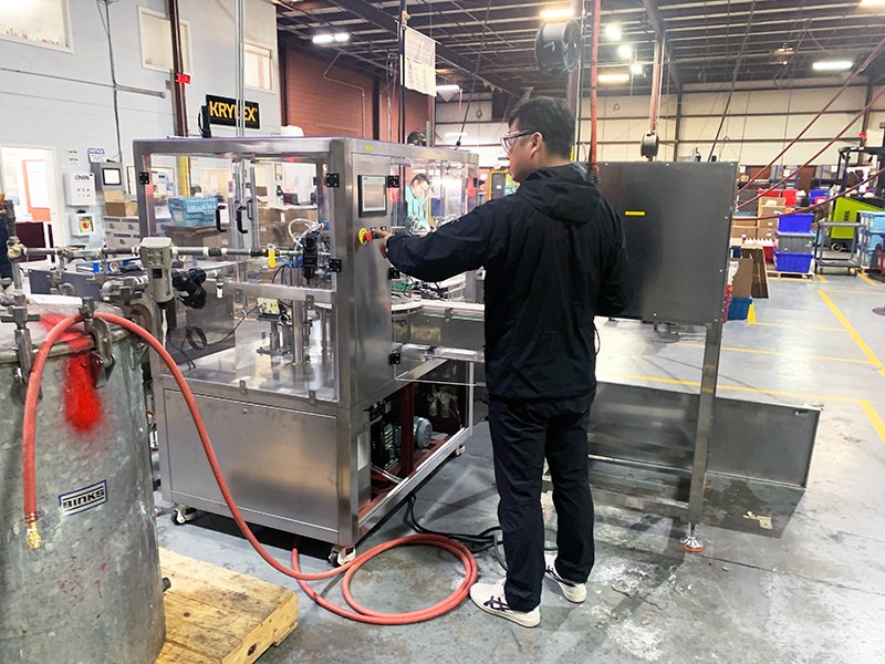
Figure 2. Counter-pressure can filling section. Source: MIC 24-6 isobaric can filling machine page.
1. Container infeed and preparation
Empty containers are spaced and transferred to the filling station. A bottle machine may use neck handling, body handling, lifting elements, or a combination selected for the bottle design. A can filler needs stable can presentation and careful positioning under the filling valve.
Rinsing may take place in an integrated rinser or in separate equipment. It is not automatically part of every filler. The required preparation depends on the container supply method, hygiene plan, and equipment scope.
Container drawings matter at this stage. Diameter, height, neck finish, cap or end specification, and material behavior affect guides, starwheels, grippers, lifting devices, and change parts.
2. Sealing, optional purging, and pressure equalization
The container forms a controlled connection with the filling valve. Depending on the product, container, and machine design, the cycle may include CO2 flushing, one or more pre-evacuation steps, or direct pressurization.
The purpose is to establish suitable conditions before filling. On a typical counter-pressure bottle filler, gas enters until the pressure in the container is compatible with the pressurized product supply. The product valve can then open without exposing the beverage to the sudden pressure drop of an atmospheric fill.
Purging sequences differ between machines. Buyers should ask the supplier to document the proposed gas path, purge sequence, oxygen-control approach, and consumption basis for the actual product and package.
3. Controlled product filling
When the liquid path opens, product flows into the container while displaced gas leaves through a defined return or exhaust path. Valve geometry and flow control are intended to reduce turbulence and manage foam.
The machine also needs a method for determining when to stop. A level filler may use a return-gas tube or probe to establish the final liquid height. A volumetric filler may use an inductive or mass flow meter to measure the quantity delivered to each container. These methods have different implications for package appearance, container variation, controls, cleaning, and maintenance.
4. Fill termination, settling, and controlled pressure release
Once the target level or volume is reached, the machine closes the product path. Many counter-pressure cycles then allow a short settling phase before reducing pressure in the container headspace.
This controlled release is often called snifting. The step prepares the container to separate from the valve without an abrupt pressure change. Its timing and control are part of the machine design. An unsuitable release sequence can allow foam to rise after filling or disturb the final level.
The equipment proposal should explain how the cycle changes for different products and container sizes. Any quoted output should state the reference product, package, and operating conditions used for the calculation.
5. Capping or can seaming
The filled container moves to its closing system. PET bottles commonly use a compatible screw-cap system. Glass bottles may use screw caps or crown closures, depending on the bottle and product. Cans require a seamer that joins the can end to the body.

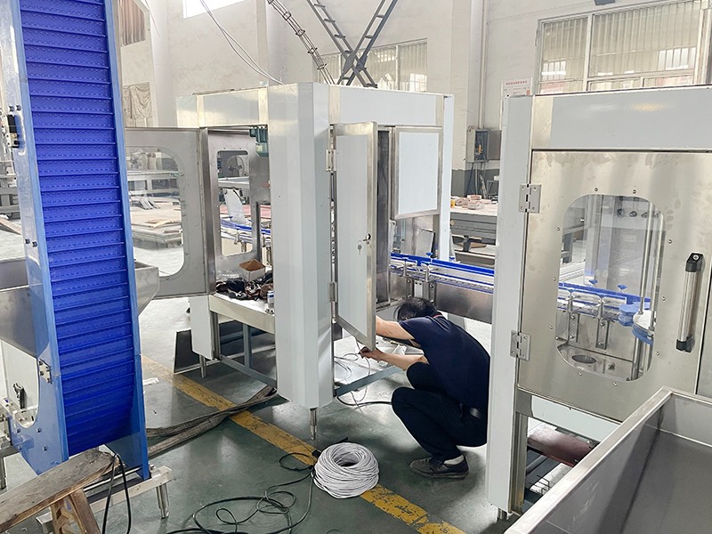
Figure 3. Can seaming section on an isobaric can filler. Source: MIC 12-1 isobaric can filler page.
Closing is closely linked to filling because delays, poor transfer, or an unsuitable closure setup can affect product retention and package integrity. Still, the closer may be integrated with the filler or supplied as a separate machine. The quotation should state which arrangement is included.
PET bottles, glass bottles, and cans: what changes
The pressure-control principle remains relevant across these package types, but the handling and closing systems are different.
|
Decision area
|
PET bottles
|
Glass bottles
|
Cans
|
|
Container handling
|
Neck or body handling depends on bottle design and machine layout
|
Stable lifting and centering must match the bottle geometry
|
Thin-walled cans require controlled feeding, positioning, and pressing against the valve
|
|
Closing method
|
Usually a compatible plastic screw cap
|
Screw cap or crown closure, depending on the bottle
|
Can end applied by a matched seamer
|
|
Main project inputs
|
Bottle drawing, neck finish, volume range, cap specification
|
Bottle drawing, finish, closure, container quality, change parts
|
Can body and end specifications, height, diameter, seaming requirements
|
|
Equipment questions
|
Blower connection, transfer method, format changeover
|
Bottle handling, breakage management, closure changeover
|
Filler-seamer matching, end feeding, seam inspection
|

Figure 4. PET bottle production and filling line layout. Source: MIC PET bottle filling machine page.
The package choice also changes container supply, conveyors, closing, inspection, labeling, packing, and spares. For multiple formats, ask whether one machine can cover them or whether the project needs change parts or separate equipment.
What equipment can be included in a carbonated beverage filling line
A complete carbonated drink filling machine line may include:
- Water treatment and product preparation
- Syrup or ingredient mixing
- Deaeration, cooling, and carbonation equipment
- PET bottle blowing or empty-container feeding
- Container rinsing or other approved preparation
- Counter-pressure filling
- Bottle capping or can seaming
- Fill-level, closure, or package inspection
- Conveying and line control
- Coding, labeling, packing, and pallet handling
Product preparation and carbonation are usually upstream of the filler, although integrated mixer-filler arrangements also exist. The quotation should state the exact boundary, including which inspection and packaging functions are supplied and how acceptance will be checked.
How to choose the right machine for a project
Start with the product, not the machine model
Prepare a product brief that identifies the beverage category, target carbonation condition, intended filling-temperature range, foam behavior, and any ingredients that could affect the product path or cleaning method. The equipment supplier can then define the suitable filling principle and valve configuration.
If several products will run on the same line, list them separately. A machine that can handle one carbonated water does not automatically have the same performance with every soft drink or future formulation.
Define the container and closure
Provide dimensioned drawings and samples where possible. For bottles, include the material, volume, neck finish, and cap or crown specification. For cans, provide the can body and end standards as well as the required seam information.
Also state every planned format. The supplier should identify common parts, change parts, adjustment points, format-change procedure, and any effect on rated output.
Compare output on the same basis
Nominal capacity is meaningful only when the reference conditions are clear. Ask each supplier to state the product, container size, carbonation condition, filling temperature, closure, and included line scope behind the quoted rate.
For a multi-format project, request expected output for each main format rather than accepting one maximum figure. Review upstream and downstream capacity as well, since the slowest or least stable section can limit actual line output.
Set the equipment boundary and site conditions
Mark the required equipment on a process flow and preliminary layout. Decide whether the project needs a standalone filler, a filling and closing block, a rinser-filler-capper, or a broader line.
Share available floor space, access restrictions, electrical supply, water, compressed air, CO2 supply, drainage, and other project utilities. The supplier should return a project-specific utility schedule rather than a generic list.
Review cleaning, changeover, and acceptance evidence
Ask how product-contact areas are cleaned, which circuits are included in CIP, which parts require manual attention, and how the machine drains. Review recipe control, change parts, tools, and operator steps for each format.
The commercial comparison should also cover the factory acceptance test, manuals, recommended spare parts, training, installation responsibilities, and the conditions used to confirm performance. These items often reveal more about project readiness than a feature list.
Common filling problems and what to check
Excessive foaming
Check product temperature, pressure stability, carbonation conditions, valve setup, filling speed profile, and the pressure-release sequence. Container condition and transfer after filling can also affect what appears at the filler discharge.
Loss of carbonation
Review pressure control from the carbonator or buffer tank through the filler, along with leaks, gas paths, and the time between filling and closing. The diagnosis should use measured product and machine data rather than a generic pressure setting.
Inconsistent fill level or volume
Confirm whether the machine controls level or volume. Then inspect the applicable return tubes, probes, flow meters, valves, product supply stability, foaming, and container variation. Calibration and maintenance requirements depend on the measuring method.
Cap, crown, or seam defects
Check the container finish, closure specification, feeding system, application settings, and inspection method. Bottle torque, crown application, and can seam evaluation require different controls and should not be grouped under one generic "capping" check.
Poor changeover repeatability
Review recipes, mechanical reference points, change-part identification, adjustment records, and the verification sample used after setup. A fast changeover has limited value if the following production run needs repeated correction.
RFQ checklist for a carbonated beverage filling project
Include the following information when requesting a quotation:
- Beverage type and the products planned for the line
- Target carbonation condition and intended filling-temperature range
- Container material and dimensioned drawings
- Container volumes and the priority reference format
- Bottle finish and closure, or can body and end specifications
- Required output for each main format
- Standalone machine, monoblock, or complete-line scope
- Upstream product-preparation and carbonation scope
- Downstream inspection, labeling, and packing scope
- Preliminary layout and available utilities
- Cleaning and changeover expectations
- Target-market compliance requirements
- Factory acceptance, documentation, spares, training, and site-support requirements
This information gives suppliers a common basis for selection. It also makes differences between quotations easier to identify before layout and contract discussions begin.
Final thoughts
A suitable carbonated filler depends on the product, package, output basis, and line scope. For a project review, send MIC those inputs through the contact page so the proposed valve cycle, measuring method, closing system, and acceptance conditions can be compared on the same basis.
Frequently asked questions
Can one machine fill both carbonated and non-carbonated drinks
Some filling systems are designed for both, but this capability must be confirmed for the specific products and packages. The supplier should explain the operating modes, valve configuration, cleaning procedure, changeover requirements, and expected output for each beverage rather than treating dual-product capability as automatic.
Does the filler control the beverage's carbonation level
The beverage is normally carbonated in upstream process equipment before it reaches the filler. The filler is designed to protect the specified carbonation during transfer and filling. Integrated mixer, carbonator, and filler arrangements are available, but their inclusion must be stated in the equipment scope.