A carbonated drink filling line should be sized from the finished product, package portfolio and required saleable output. Filler speed is one input, while the connected process and packaging sections determine what the factory can ship. A clear design basis lets suppliers configure the same project scope and gives buyers a fair way to compare proposals.

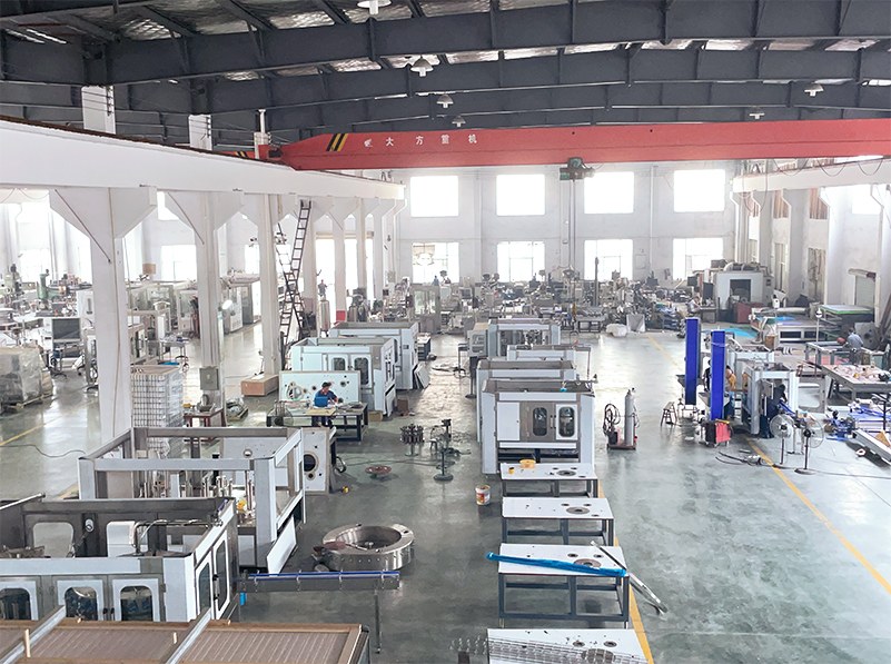
Figure 1. A complete line connects product preparation, filling, conveying and final packaging
Source: MIC drink filling line
Start with the beverage specification
List every product planned for the line, including the beverage category, recipe family, target carbonation, intended filling temperature range and ingredients that affect foaming or cleaning. These conditions shape product preparation, cooling, carbonation, buffer capacity and filler selection. Carbonated beverages use pressure-controlled filling to limit CO2 loss and excessive foaming, as described in KHS technical material for carbonated soft drinks.
A multi-product line needs a separate entry for each formula. Grouping every SKU under "soda" hides differences in carbonation, flavor residue, cleaning duty and batch scheduling. The product matrix should also identify quality checks that affect release, such as soluble solids, dissolved CO2, fill quantity and closure integrity, according to the plant's approved product specification.
For a closer look at pressure equalization and the filling cycle, use Internal Link Pending: How does a carbonated beverage filling machine work?. This guide stays at line level and uses the product specification to define equipment scope.
Freeze the package before choosing capacity
The package determines how containers enter the line, how they are supported at the filler, which closing system is required and how finished units are inspected and packed. A nominal volume alone is insufficient. Suppliers need dimensioned drawings, physical samples when available, the closure specification, label format, secondary pack and pallet pattern.
|
Decision area
|
PET bottle
|
Glass bottle
|
Aluminum can
|
|
Container supply
|
Preform blowing on site or purchased empty bottles
|
New or returnable bottles, with the corresponding receiving and preparation route
|
Depalletized empty cans with controlled feeding
|
|
Handling basis
|
Bottle geometry, neck finish, base and material behavior
|
Bottle dimensions, finish, rigidity and breakage controls
|
Can diameter, height, end specification and protection from dents
|
|
Closing system
|
Compatible plastic closure and cap feed
|
Crown or screw closure according to the approved bottle
|
Matched can end and seamer
|
|
Inspection focus
|
Bottle condition, fill, cap and package stability
|
Bottle condition, fill, closure and broken-glass controls
|
Can condition, fill, end supply and seam quality
|
|
Changeover inputs
|
Bottle, neck, cap, label and pack formats
|
Bottle, closure, label and pack formats
|
Can body, end, label or decoration and pack formats
|


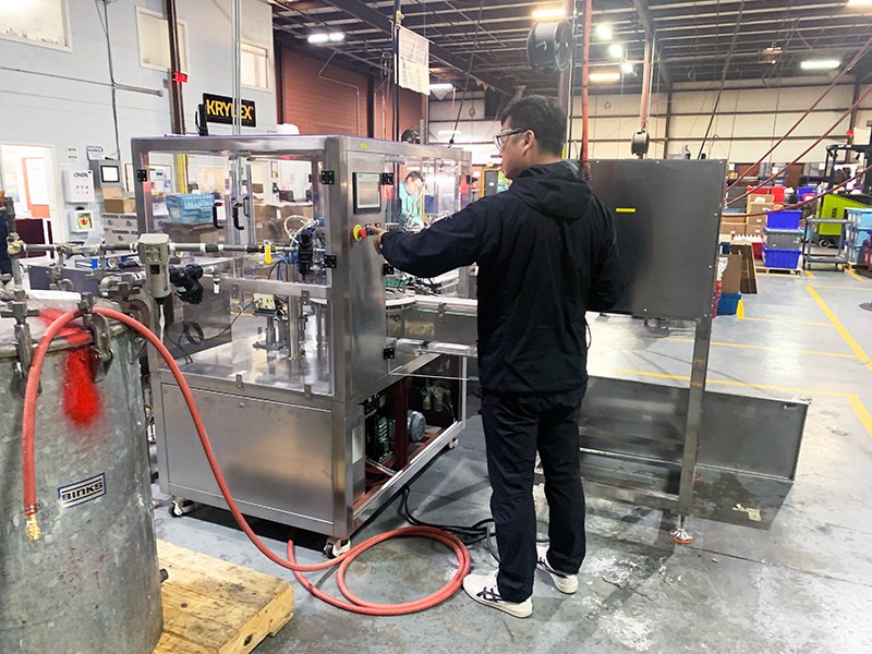
Figure 2. Bottle filling and capping equipment at left and can filling and seaming equipment at right
Source: MIC carbonated soft drink filling machine and MIC soft drink can filling machine line
Official equipment examples show why these routes need separate engineering. KHS describes pressurized filling for carbonated products in glass bottles. The Krones Modulfill VFS-C uses can positioning, pressing and flow-meter monitoring in a can-specific design. Both examples are specific to the manufacturers and equipment cited.
A project with more than one package material can share parts of the process section, including syrup preparation or carbonation where the approved design permits it. Container handling, closing and inspection remain package-specific. The proposal should identify the shared modules and the equipment assigned to each route.
Convert demand and SKU mix into net line output
Begin with the number of saleable units required by week or production campaign. Split the demand by SKU because container size, closure, label and secondary pack can change the sustainable rate. Then define the production calendar, including shifts, planned cleaning, format changes, maintenance and other scheduled stops.
Use this calculation:
Required average saleable output = planned saleable units / available production hours
Suppose a plant needs 280,000 saleable bottles per week and has 70 production hours after scheduled cleaning and changeovers. The required average is 4,000 saleable bottles per hour. This figure is a demand rate, not a machine rating. The project team must still account for minor stops, speed losses, rejects and recovery after interruptions when setting the required running rate.
Keep these losses visible by using plant data for each SKU where reliable records exist. A new project should use agreed planning assumptions and require the supplier to state them. The Weihenstephan Standards define current machine speed as a measured value with an engineering unit such as bottles per hour; a current speed reading does not establish sustained saleable line output.
For every major SKU, ask for four separate figures:
- rated machine speed under stated reference conditions;
- expected line speed with all connected equipment in scope;
- the basis used to convert running speed into saleable output;
- the test method that will verify the contracted result.
Size product preparation to support filling
A filler cannot maintain output when product preparation runs short. Build a process flow from water treatment and syrup preparation through blending, cooling, carbonation, buffer storage and filling. Assign a design flow, batch logic and responsibility boundary to every section.
Water treatment follows the source-water analysis and finished-product requirement. Syrup and blending capacity follows recipe size, batch frequency and the number of products scheduled between cleanings. Cooling and carbonation are then matched to the beverage flow and approved product conditions. The buffer plan should explain the response to normal filler stops and the permitted product-hold conditions.
KHS carbonated soft drink systems and Sidel PET CSD line material both present filling as part of a connected process and packaging system. Their equipment data describes their own products and is not a specification for MIC equipment.
Match filling and closing technology to the package
The approved product and package define the filling and closing block. The supplier should identify the proposed filling principle, measuring method, container handling and closure system for each SKU. The same document should state the product, container, closure and operating conditions behind every quoted speed.
A project may use a standalone filler, a filler-closer block, a rinser-filler-capper or a larger integrated system. Define the limits of supply for the selected arrangement, including container preparation, cap or end feeding, product piping, cleaning connections, inspection, guarding, controls and transfer equipment at each interface.

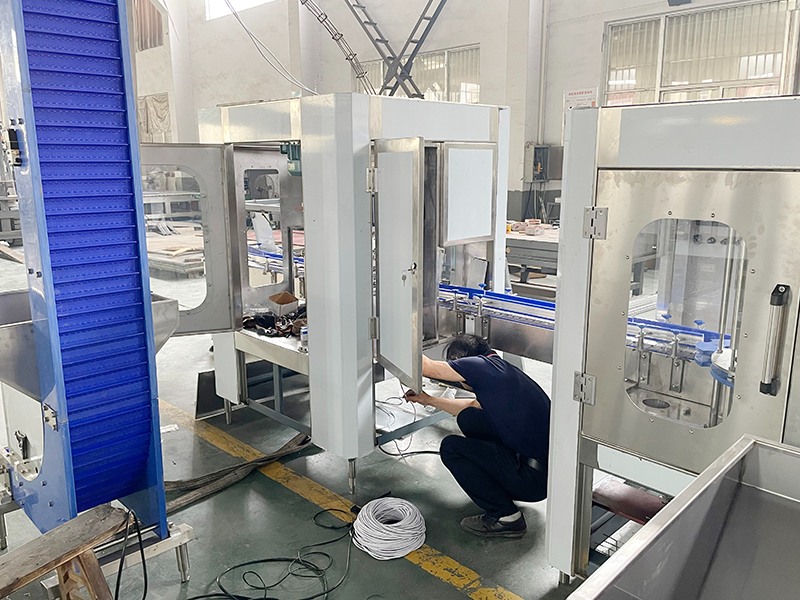
Figure 3. Filling valves and container handling must match the approved package
Source: MIC carbonated drink production line
MIC's carbonated drink filling machine page can be used to review commercial equipment categories. Final model selection requires an approved product and package matrix.
Balance the connected line around saleable output
Line balance starts with the required output for each SKU and checks whether every section can support it under the same conditions. A fast filler adds little capacity when the carbonator, labeler or packer repeatedly starves or blocks it. Conveyors and accumulation can absorb short disturbances when the layout assigns them a defined operating purpose.
|
Line section
|
Sizing question
|
Evidence to request
|
|
Container supply
|
Can it feed the reference container continuously at the required rate?
|
SKU speed table, buffer logic and recovery sequence
|
|
Filling and closing
|
Which product, container and closure support the quoted speed?
|
Rating basis, change parts and closure checks
|
|
Inspection and coding
|
Which defects are detected and where are rejects sent?
|
Test pieces, challenge method and reject route
|
|
Labeling and packing
|
Can approved materials run at the same line rate?
|
Material samples, pack pattern and speed basis
|
|
Conveying and controls
|
How does the line respond to starved and blocked machines?
|
Control narrative, accumulation locations and restart logic
|
Measure final performance at a point that represents saleable units, then define how rejects, rework and incomplete packs are counted. This prevents a filler discharge count from being reported as finished output when downstream losses remain outside the calculation.
Choose automation by operating task
Automation should remove a defined constraint or control a defined risk. Start with the work operators and technicians must perform during normal production, product change, material replenishment, fault recovery and quality checks.
Recipe control can reduce manual setpoint entry across repeated SKUs. Automated container and packaging-material handling can reduce frequent intervention at high-throughput points. Inspection and reject systems can identify specified package faults, while production data can show where the line is starved, blocked or stopped. Each function needs a stated detection method, response and operator responsibility.
Separate three control levels in the specification: machine PLC and HMI functions, coordination between connected machines, and production-data exchange with higher-level systems. The proposal should describe which actions remain manual, how the system recovers after a stop and what data is available for production review.
Confirm utilities, cleaning and acceptance conditions
Prepare a utility schedule for electricity, service air, high-pressure air where bottle blowing is included, CO2, cooling, process water, cleaning water, drainage and chemicals. Each entry should identify the required condition, connected equipment, peak or operating basis, connection point and responsible party. Confirmed values belong in the project proposal after equipment and site conditions are fixed.
The cleaning plan should map product-contact circuits, manual cleaning tasks, change parts, drain points and restart checks. Multi-flavor production also needs an approved sequence for recipe changes and product release. These details affect available production time and should be included in the capacity model.
Define the factory acceptance test before the purchase order. The FAT protocol should name the reference product or agreed test medium, container and closure, line scope, target rate, run duration, planned-stop rules, reject treatment, inspection checks and evidence to retain. Site acceptance then verifies the installed system with the agreed utilities and connected equipment.
Prepare a project brief for the configuration proposal
Send the same design basis to every shortlisted supplier:
- Product list, recipe families, target carbonation and filling temperature conditions.
- Container drawings and samples, capacities, neck or can-end specifications and closures.
- Label, code, secondary pack and pallet pattern for each SKU.
- Saleable demand, shifts, batch sizes, cleaning and changeover plan.
- Required scope, including product preparation, container supply, filling, inspection and packing.
- Factory drawing, material flow, maintenance access and installation constraints.
- Available utilities and the buyer-supplier responsibility matrix.
- Required controls, production data, documents, spares, training and acceptance tests.
Ask suppliers to return an itemized scope, SKU speed table, utility list, layout, interface schedule and list of deviations. This format exposes missing equipment and different assumptions before price comparison.
Final thoughts
For an initial configuration, submit the beverage specification, packaging formats, SKU demand and available factory utilities through the MIC drink filling line page.
Frequently asked questions
Which SKU should be used as the reference for line sizing
Use the SKU that best represents the project's commercial priority and technical constraint. The highest-volume SKU may set the main capacity target, while a larger container, difficult label or complex pack can set the slowest operating case. Request a speed and changeover table for every major SKU instead of applying one reference rate to the whole portfolio.
Should a new plant buy extra capacity for future growth
Plan expansion through documented demand scenarios. The layout, utilities, conveyors, control architecture and product-preparation area can reserve defined expansion paths even when the first installation is smaller. Set the spare-capacity margin from forecast confidence, shift options, investment limits and the cost of future modification.
Can one carbonator support several flavors
That depends on recipe compatibility, batch scheduling, cleaning boundaries, buffer strategy and the carbonator's approved operating range. List each product and the planned sequence, then ask the process supplier to document changeover steps, residual-product control and the conditions required before the next batch is released.
Is the largest container always the slowest SKU
Container volume is only one constraint. Bottle or can stability, filling conditions, closure application, label handling, pack pattern and change parts can set a lower rate for another format. Require a separate operating basis for each major SKU and verify the limiting machine in the connected line.
What makes two carbonated drink line quotations difficult to compare
Differences usually appear in equipment boundaries, reference SKUs, output definitions, utilities, local supply, test duration and service scope. Give each supplier the same RFQ and require a compliance table that marks every item as included, optional, excluded or requiring clarification.
What is the difference between FAT and SAT
FAT checks the agreed equipment and functions before shipment under a defined factory test protocol. SAT checks the installed system at site with the approved utilities and connected equipment. The contract should state the acceptance limits, evidence, deviation process and retest responsibility for both stages.